The Most Complete Example of EIGRP Experiment Configuration in History
 Introduction
EIGRP is a Cisco proprietary protocol. It is a protocol composed of two routing protocols: distance vector and link state. That is, like the distance vector protocol, EIGRP gets update information from its neighboring routers; like the link state protocol, it saves a topology table, and then selects an optimal acyclic path through its own DUAL algorithm. EIGRP is not like the traditional distance vector protocol, EIGRP has a fast convergence time, and does not need to send periodic routing updates; unlike the link state protocol, EIGRP does not know what the entire network is like, it can only rely on neighbors to announce Information. EIGRP uses the same routing algorithm DUAL (Diffusion Update Algorithm) as IGRP. The DUAL mechanism is the core of EIGRP, through which loop-free paths are realized. The internal EIGRP management distance is 90 and the external EIGRP management distance is 170, which supports equal and non-equivalent load balancing. In IP packets, the EIGRP protocol field is 88.
Glossary:
Metrics: EIGRP use bandwidth (bandwidth), delay (delay), reliability (reliability), loading (loading), maximum transmission unit
(MTU) These five values are used to calculate the metric. By default, only bandwidth and delay are in effect. The calculation formula is-EIGRP metric = [(10 ^ 7 / path
Lower bandwidth on +) + (sum of all delays)] × 256; EIGRP metric = IGRP metric × 256.
Feasible Distance: The smallest metric to reach a destination.
Advertisement Distance (Advertise Distance): The minimum metric value advertised by the neighboring router to reach a certain destination.
Feasible Condition: The condition that the advertised distance (AD) is less than the feasible distance is AD <FD, which means that the neighboring router reaches the destination
The metric of the ground must be smaller than the metric of the local router to reach the destination. This condition can ensure that a path is loop-free.
EIGRP Successor: A directly connected neighbor router that satisfies the FC and passes the path with the smallest metric value to its destination
By device. The successor router is used as the next hop to forward the message to the destination.
Feasible Successor: A neighbor router that meets the FC and has the second lowest metric to the destination router. Be the master
When route S is unavailable, FS is used to replace the main route, so it is saved in the topology table and used as a backup route.
Active state / active routing (active state): It is a state of searching for FS. When the router loses S and no FS is available, the
The route entered an active state and is an unavailable route. When a route is active, the router sends a query to all neighbors to find
Find another route to this destination.
Passive state / passive routing (passive state): It is a state where the correct route currently reaches the destination. When the router loses S, there is a
When an FS is found, or when another S is found, the route enters a passive state and is an available route.
Neighbor relationship: EIGRP establishes a neighbor relationship through hello packets. The transmission interval of hello packets is 60 seconds on low-speed links and 5 seconds on high-speed links.
If the hello packet is not received within a period of time, the neighbor relationship is reset. This time is the hold time, and the default hold time
It is three times the hello time. Both times can be modified manually. When establishing a neighbor relationship, the K value and the self-made system number must be the same. can
Check the neighbor relationship through show ip eigrp neighbor.
Experimental topology
Introduction
EIGRP is a Cisco proprietary protocol. It is a protocol composed of two routing protocols: distance vector and link state. That is, like the distance vector protocol, EIGRP gets update information from its neighboring routers; like the link state protocol, it saves a topology table, and then selects an optimal acyclic path through its own DUAL algorithm. EIGRP is not like the traditional distance vector protocol, EIGRP has a fast convergence time, and does not need to send periodic routing updates; unlike the link state protocol, EIGRP does not know what the entire network is like, it can only rely on neighbors to announce Information. EIGRP uses the same routing algorithm DUAL (Diffusion Update Algorithm) as IGRP. The DUAL mechanism is the core of EIGRP, through which loop-free paths are realized. The internal EIGRP management distance is 90 and the external EIGRP management distance is 170, which supports equal and non-equivalent load balancing. In IP packets, the EIGRP protocol field is 88.
Glossary:
Metrics: EIGRP use bandwidth (bandwidth), delay (delay), reliability (reliability), loading (loading), maximum transmission unit
(MTU) These five values are used to calculate the metric. By default, only bandwidth and delay are in effect. The calculation formula is-EIGRP metric = [(10 ^ 7 / path
Lower bandwidth on +) + (sum of all delays)] × 256; EIGRP metric = IGRP metric × 256.
Feasible Distance: The smallest metric to reach a destination.
Advertisement Distance (Advertise Distance): The minimum metric value advertised by the neighboring router to reach a certain destination.
Feasible Condition: The condition that the advertised distance (AD) is less than the feasible distance is AD <FD, which means that the neighboring router reaches the destination
The metric of the ground must be smaller than the metric of the local router to reach the destination. This condition can ensure that a path is loop-free.
EIGRP Successor: A directly connected neighbor router that satisfies the FC and passes the path with the smallest metric value to its destination
By device. The successor router is used as the next hop to forward the message to the destination.
Feasible Successor: A neighbor router that meets the FC and has the second lowest metric to the destination router. Be the master
When route S is unavailable, FS is used to replace the main route, so it is saved in the topology table and used as a backup route.
Active state / active routing (active state): It is a state of searching for FS. When the router loses S and no FS is available, the
The route entered an active state and is an unavailable route. When a route is active, the router sends a query to all neighbors to find
Find another route to this destination.
Passive state / passive routing (passive state): It is a state where the correct route currently reaches the destination. When the router loses S, there is a
When an FS is found, or when another S is found, the route enters a passive state and is an available route.
Neighbor relationship: EIGRP establishes a neighbor relationship through hello packets. The transmission interval of hello packets is 60 seconds on low-speed links and 5 seconds on high-speed links.
If the hello packet is not received within a period of time, the neighbor relationship is reset. This time is the hold time, and the default hold time
It is three times the hello time. Both times can be modified manually. When establishing a neighbor relationship, the K value and the self-made system number must be the same. can
Check the neighbor relationship through show ip eigrp neighbor.
Experimental topology
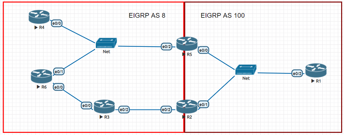 IP address planning
1. The IP address segment in the topology is adopted: 172.8.AB.X / 24
2. Where AB is the combination of two router numbers, for example: AB between R3-R6 is 36, X is the router number, for example: R3 X = 3
3. The network segment between R1 / R2 / R5 is: 172.8.123.X / 24, where X is the router number.
4. The network segment between R4 / R5 / R6 is: 172.8.100.X / 24, where X is the router number.
5. All routers have a loopback 0 interface, the address format is: X.X.X.X / 32, where X is the router number.
Testing Requirement
IP address planning
1. The IP address segment in the topology is adopted: 172.8.AB.X / 24
2. Where AB is the combination of two router numbers, for example: AB between R3-R6 is 36, X is the router number, for example: R3 X = 3
3. The network segment between R1 / R2 / R5 is: 172.8.123.X / 24, where X is the router number.
4. The network segment between R4 / R5 / R6 is: 172.8.100.X / 24, where X is the router number.
5. All routers have a loopback 0 interface, the address format is: X.X.X.X / 32, where X is the router number.
Testing Requirement
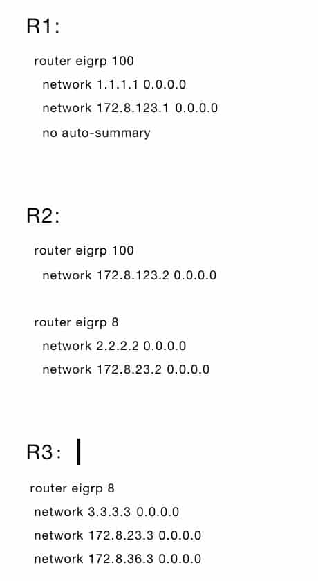
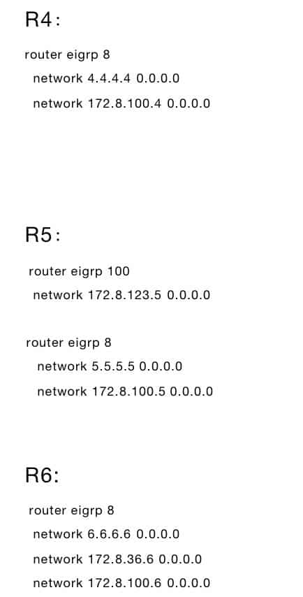
- R4 / R5 / R6 are connected through a Layer 2 switch. According to the experimental topology diagram, declare the router interface to the corresponding EIGRP process. If there is no specific description, you can declare it arbitrarily. It is required to turn off automatic aggregation.
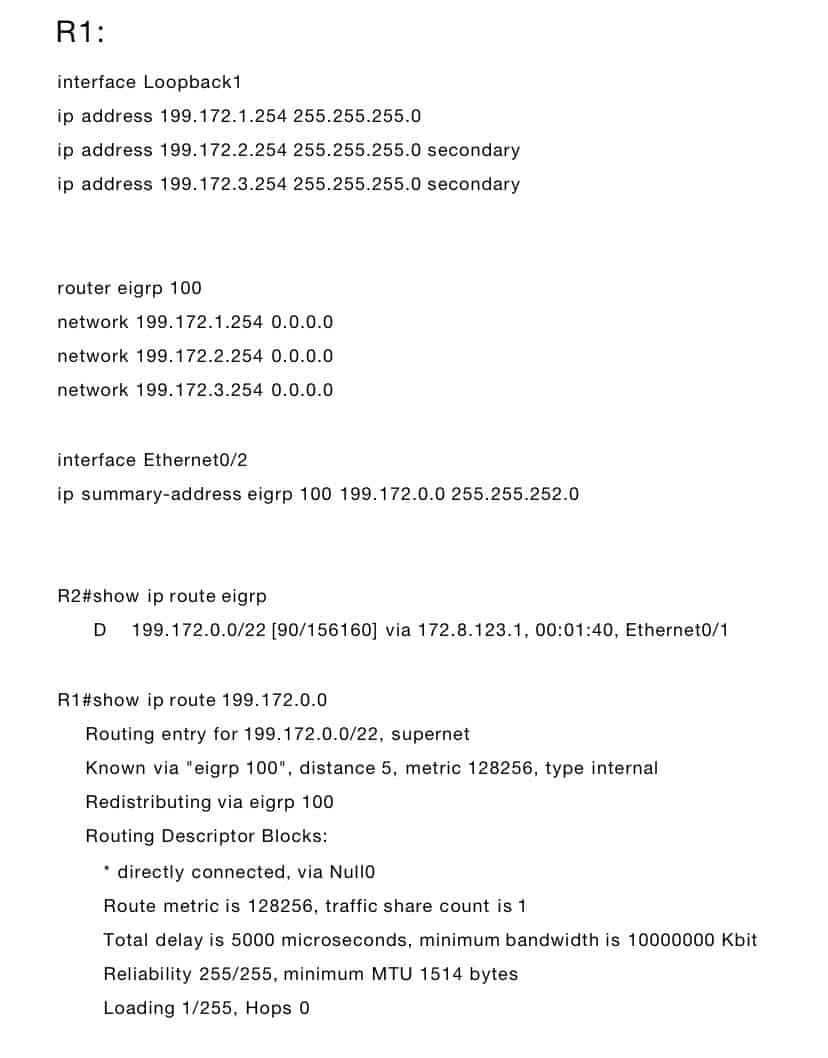
- There is a Loopback 1 interface on R1. The IP is: 199.172.1.254/24, 199.172.2.254/24, 199.172.3.254/24 (using the secondary method to configure IP), and announce them to EIGRP 100. To summarize the addresses of R1's Loopback1 interface on R1 and observe the routing table on R2.
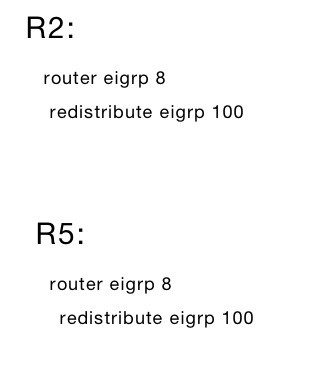
- The router in EIGRP AS 8 is required to receive the summary route of R1.
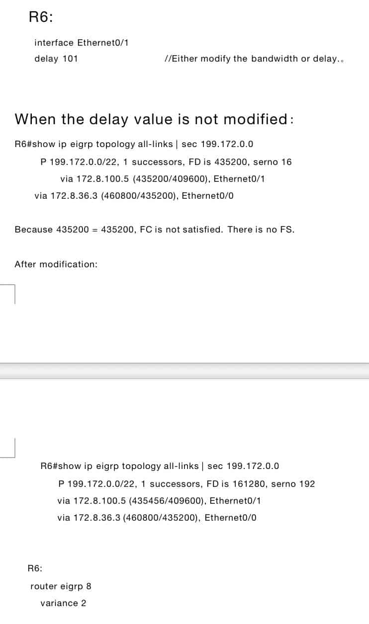
- This summary route from R6 to R1 is required to achieve unequal cost load balancing.
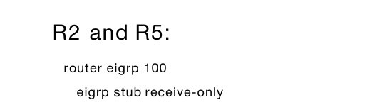
- Configure R2 and R5 so that they will not receive any EIGRP query information under the EGRIP 100 process, and will not send any routing information about them to their EIGRP 100 neighbors.
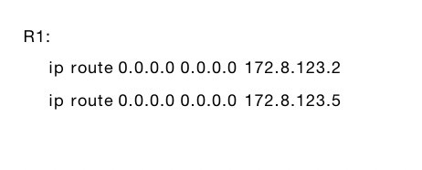
- It is required to use up to 2 static routing entries to achieve inter-network communication.
- R4 / R5 / R6 are connected through a Layer 2 switch. According to the experimental topology diagram, declare the router interface to the corresponding EIGRP process. If there is no specific description, you can declare it arbitrarily. It is required to turn off automatic aggregation.
- There is a Loopback 1 interface on R1. The IP is: 199.172.1.254/24, 199.172.2.254/24, 199.172.3.254/24 (using the secondary method to configure IP), and announce them to EIGRP 100, using manual summary To summarize the addresses of R1's Loopback1 interface on R1 and observe the routing table on R2.
- The router in EIGRP AS 8 is required to receive the summary route of R1.
- The summary route from R6 to R1 is required to achieve unequal cost load balancing.
- Configure R2 and R5 so that they will not receive any EIGRP query information under the EGRIP 100 process, and will not send any routing information about them to their EIGRP 100 neighbors.
- It is required to use up to 2 static route entries to achieve inter-network communication.

Recommended Reading: