-
- Huawei
- 912
- 2024-01-18
Are you looking for someone who can take you on a deep informational ride and gives you all the essential knowledge and guidance on Huawei Certification? Then, this will help you to a great
extent. About Huawei Huawei being a foremost global provider of information and communications technology (ICT) infrastructure and smart devices was being founded in 1987. In this digital world, Huawei is the most established in the technology sector, is on the path to bring digital technologies in everyone’s life, home, and organization so as to make the work easy and fully connected, intelligent world. Huawei serves more than 3 billion people around the world and is operating in more than 170 countries and regions.
Due to the increasing demand for enterprises and the inadequate supply of ICT professionals, Huawei has started up a leading ICT talent development system and certification standards so as to provide comprehensive learning materials and advanced paths, as well as scientific evaluation standards for beginners who want to join ICT industry.
Huawei is embryonic new ICT talents using application capabilities, composite innovation, and effective growth for the industry. Huawei Certification is on the way of creating Platform+AI+Ecosystem development strategy, and its new ICT technology headlining Cloud-Pipe- Device coactions. Huawei Certification is the only certification organization that covers up all ICT technologies in the industry that consist of 3 categories:
ICT Infrastructure Certification
Platform and Service Certification
ICT Vertical Certification
Huawei Certification provides three levels of certification:
Huawei Certified ICT Associate(HCIA)
Huawei Certified ICT Professional (HCIP)
Huawei Certified ICT Expert(HCIE)
Levels: Huawei Certified ICT Associate (HCIA): This certification program is designed and is awarded to the engineers who can install, configure, and operate ICT devices, and fix faults in a technical field.
Huawei Certified ICT Professional (HCIP): This certification program is designed for the engineers who have the expertise and well skilled in ICT technical field and is awarded to senior engineer.
Huawei Certified ICT Expert(HCIE): This is Huawei’s topmost level of ICT technical certification and is awarded to those engineers who are highly proficient and highly skilled in ICT and have great experience in practice. About Huawei Certification ICT Infrastructure Certification emphasizes on the hardware and software components of ICT, offers certifications in 11 technical fields - Data Center, Storage, Intelligent Computing, Routing and Switching, WLAN, Security, SDN, Transmission, Access, LTE, and 5G. Engineers who are successful in achieving ICT Infrastructure Certification will be able to exhibit their knowledge of ICT infrastructure planning, construction, and maintenance.
Platform and Service Certification would be emphasizing on new ICT such as AI, IoT, and Cloud and offers certifications in 6 technical fields - Cloud Computing, Cloud Service, Big Data, AI, IoT, and Enterprise Communication. Being the Platform and Service Certification holder indicates that the certificate holder is able to amalgamate business, technologies, and applications. Besides that, Platform and Service Certification holders will be capable to make and operate cloud platforms and architectures in addition to developing new technical applications based on cloud platforms.
ICT Vertical Certification emphasizes on a detailed understanding of the ICT industry and offers certifications in 2 technical fields - Finance and Public Safety. As a result, ICT Vertical Certified shows an understanding of ICT and other pertinent industries. Benefits of Huawei Certification Consolidates your technical foundation: Huawei Certification coalesce theory and practical. It builds up a strong technical foundation and thoroughly evaluates the knowledge and skills of ICT specialists.
Keeping up with the trends: Huawei Certification incorporates cutting-edge ICT trends, keeping updated on developing areas like Artificial Intelligence (AI) Internet of Things (IoT).
Improve employment competitiveness: Achieving Huawei Certification shows that you have great ICT knowledge and you are highly skilled. It will brighten your future and perk-up your employment competitiveness in Huawei ecosystem.
If you wish to achieve Huawei Certification in single attempt, you should check out the training courses offered by the SPOTO Club.
-
- PMP
- 581
- 2024-01-15
The PMP Exam is the first and the most important step for Project management Professional (PMP) certification. The PMP is widely recognizing certification for Project Managers of MNC's which helps them in acquiring a good hike in their salaries.
Acquiring Project Management Professional (PMP) is one of the most intelligent decisions of the professionals for their future as this course gives them the skills required to be one step ahead and being the top-notch certified project managers required by the global market.
There are various ways to prepare for the PMP examinations which include a wide range of books, e-books, free online study material or enrolling in various online courses available with varied ranging course fees. For self-studying or extra reference, PMP books are the best option as they are easily available and accessible both online and offline.
The following are among the best books for the PMP exam Prep which are mentioned with their editions and the author's name.
3 best PMP exam books to refer to passing PMP exams.
PMP Exam Prep book
This is one of the best book written by the group of PMP's, having experience of several years in various fields of professional management while working with several multinational companies, for aspiring PMPs. The content of the book provides the latest changes and development on various strategies of PMP.
This book is best in terms of the price and the content being of the gold standard for the exam prep. It can be always preserved for future reference once the PMP exams are cleared for various management projects. The book immense knowledge of project management areas, process groups, various inputs on the topic. This book no doubt finds its top position in various lists of books for PMP Exam prep.
2 Rita Mulcahy’s PMP Exam Prep Book,9th Edition by Rita Mulcahy’s
The second book is pretty much easy to follow for the PMP exam preparation. It is one of the excellent books on the list. It has a lot of practice questions probably on every topic going to be tested in the PMP exam along with useful tips and techniques to crack hard of the exam. The lucidity of the book allows one to directly connect to the author and her thoughts on the subject. This book is much easier to follow as compared to the previous book on the list as its content is simple yet invaluable.
3.The PMP Exam: How to Pass on Your First Try, Sixth Edition by Andy Crowe
This book has the most extensive and wide-ranging details for the exam prep, especially by professionals. Its in-depth guide to concepts and the practice sections in a marvelous add-on.
The author, Andy Crowe, has 25 years of experience in the field of Project Management making him much more versatile in his writing and sharing his personal experiences for the growth of budding PMPs.His training company helps in the empowerment of the other project professionals
The uniqueness of the book is due to its inclusion of the chapter on the Role of Project Manager, discussing various tips and techniques on how can one effectively pass the exam. The book includes a whopping 400 practical exam questions, chapter-end quizzes, links to various videos that go up to 60 and finally a sample of mock exams.
In a nutshell.
Every PMP prep book has its pros and cons and can be always used in combination to overcome the shortcomings. Depending upon the purpose these books help in updating one knowledge and professional skills, for personal upgrading of the professional skills or to learn for the exams. Along with these books, you should also check out the training courses offered by the SPOTO Club, for achieving success.
-
- Cisco
- 596
- 2024-01-18
Simply asking, DevOps (development and operations) is considered to be a software development phrase utilized for describing a type of agile relationship between Development and IT Operations. The goal of DevOps is considered to improve communication, processes, and collaboration between the various roles in the software development cycle for improving and speeding up software delivery.
DevOps would be developing in the software development as well as IT operations world around 2009, and during that time, agile would be fairly well established in the movement away from waterfall development to continuous, iterative development cycles. The DevOps movement would be emphasizing integration between software developers as well as IT operations, rather than seeing these two groups as silos who would be passing things along but don’t really work together, DevOps would be recognizing the interdependence of software development as well as IT operations, and this approach would be able to help an organization produce software as well as IT services more quickly, with frequent iterations. So, if you wish to acquire more knowledge about the same, check out the training courses offered by the SPOTO Club.
What Are the Measurable Benefits of DevOps?
DevOps would be aiming at establishing a culture as well as an environment where building, testing, as well as releasing software could happen rapidly, frequently, as well as more reliably, and in a DevOps environment, cross-functionality, shared responsibilities, and trust would be promoted. One concrete benefit of DevOps is an observed decrease in development as well as operations cost.
Other measurable benefits of DevOps would be including:
Improved Defect Detection
Increased Release Velocity
Reduced Deployment Failures and Rollbacks
Reduced Time to Recover upon Failure
Shorter Development Cycle
Etsy
For its first numerous years, Etsy would be struggling with slow, painful site updates that frequently would be causing the site to go down. In addition to frustrating visitors, any downtime would be impacting sales for Etsy's millions of users who would be selling goods through the online marketplace as well as risked driving them to a competitor. With the assistance of a latest technical management team, Etsy was able to transition from its waterfall model, which would be produced four-hour full-site deployments twice weekly, for a more agile approach.
Today, it would be having a fully automated deployment pipeline, as well as its continuous delivery practices, which have reportedly resulted in more than 50 deployments a day with fewer interruptions. And though Etsy would be having no DevOps group per se, its commitment to collaboration across teams would have made the company a model of the DevOps framework.
Adobe
Adobe's DevOps transformation took a sharp turn five years ago when the company moved from packaged software to a cloud services model as well as was suddenly faced with making an uninterrupted series of small software updates rather than big, semi-annual releases. In order to maintain the required pace, Adobe would be utilizing CloudMunch's end-to-end DevOps platform for automating and managing its deployments. Because it would be integrating with a variety of software, developers could continue to use their preferred tools, as well as its multi-project view would be allowing them to see how a change to anyone Adobe product would be affecting the others.
In Summary
DevOps found initial traction within lots of large public cloud service providers. With modern applications running in the cloud, much of what utilized for considering the infrastructure is now considered to be a part of the code. DevOps would be helping you to ensure frequent deploys with a low failure rate. DevOps practices as well as procedures would be leading to smoothing out the typically bumpiest aspects of software deployment and development.
For more details on DevOps, visit the IT exam training section available at the SPOTO Club.
-
- Cisco
- 684
- 2024-01-16
Before we would be beginning, let's gain the pedantic: at this point in time, artificial intelligence is considered to be a purely theoretical concept. True AI, a sentient computer capable of the initiative as well as human interaction, remains within the realm of science fiction. The AI research field is considered to be full of conflicting ideas, and it isn’t clear whether we could actually build a machine that could be replicating the inner workings of the human brain. For getting details regarding the AI, you should gain the study dumps which are being offered at the SPOTO Club, to acquire success.
In the data center
The impact of AI on data centers could be divided into two broad categories – the impact on hardware as well as architectures, as the users would be beginning adopting AI-inspired technologies, and the impact on the management as well as operation of the facilities themselves.
We would be beginning with the first category: turns out that machine learning as well as services such as speech and image recognition which would be requiring a new breed of servers, equipped with novel components like the GPUs (Graphics Processing Units), FPGAs (Field-Programmable Gate Arrays) and ASICs (Application-Specific Integrated Circuits). All of these would be requiring massive amounts of power, as well as producing massive amounts of heat.
Nvidia, the world’s largest supplier of graphics chips, would have just announced DGX-2, a 10U box for algorithm training that would be including 16 Volta V100 GPUs along with two Intel Xeon Platinum CPUs as well as 30TB of flash storage. DGX-2 delivers up to two Petaflops of compute, as well as consuming a whopping 10kW of power – more than an entire 42U rack of traditional servers.
And Nvidia isn’t considered to be alone in pushing the envelope on power density: DGX-2 would be actually a reference design, as well as server vendors have been given permission for iterating and creating their own variants, some of which might be even more power-hungry. Meanwhile, Intel would be just confirming the rumors that it’s working on its own data center GPUs which would be expected to hit the market in 2020.
As power densities go up, so does the amount of heat that would be required to be removed from the servers, and this would inevitably result in the growing adoption of liquid cooling.
For the data center
But machine learning is considered to be also useful in the management of the data center, where it could help you to optimize energy consumption as well as server use. For example, an algorithm could spot under-utilized servers, automatically moving the workloads as well as either switch off idle machines for conserving energy or rent them out as part of a cloud service, which would be creating an additional revenue stream.
American software vendor Nlyte would have just partnered with IBM for integrating Watson perhaps the most famous ‘cognitive computing’ product to date into its DCIM (Data Centre Infrastructure Management) products.
Beyond management, AI could be improving physical security by tracking individuals throughout the data center utilizing CCTV, as well as alerting its masters when something would be looking out of order.
I think it would be a safe bet for saying that every DCIM vendor would be eventually offering some kind of AI functionality. Or at least something they would be calling AI functionality.
If you wish to explore more about the impact of the AI in the Data Center, you should acquire the training courses which are being offered at the SPOTO Club. When it comes to gain IT Certification, SPOTO Club’s Training Courses are considered to be the best one.
-
- Cisco
- 569
- 2024-01-18
Cisco executive says SD-WAN, Wi-Fi 6, multi-domain control, virtual network administration, and the developing role of network engineers would be considered to be enormous in 2020.
This year Cisco would have revamped a part of its most fundamental certifications as well as career improvement tools with an ultimate objective for addressing the rising software-oriented network environment. Maybe the best addition is the new set of expert certifications for developers which would be utilizing Cisco’s developing DevNet engineer community.
5G and Wi-Fi 6
As 5G and Wi-Fi 6 would be additionally fused into our network systems as well as devices, the technology and devices would be quickly catching up for individuals’ longing want and desire to gain to phenomenal speed access anyplace at whatever point. With more people ready to interface more devices as well as get steadier, faster, and more remote reaching internet access as well even in remote districts as well as indoor spaces not utilized to support the demand for internet usage is simply going to grow. Adding to those impacting processing speeds would be coming to at the domain of 1 gigabit for each second as well as bandwidth ability for serving more devices simultaneously with much more prominent stability, as well as you would be having the mix for a critical evolution in our digital landscape of internet everywhere.
SD-WAN and WAN optimization
The Network World’s would be reviewing found that 58 percent of respondents said SD-WAN could be improved bandwidth speed efficiency, and 55 percent said it would be growing connectivity options. 48 percent said it would be encouraging hybrid cloud as well as 41 percent said it would supporting multi-cloud adoption. The Network World survey found that the extended utilization of containers as well as cloud-based applications that would require access from the edge would be also driving the utilization of SD-WAN technologies.
Extensive multi-domain networks
The advanced networks would be the multi-domain which would be requiring an automation strategy that would be containing diverse programmable constructs as well as interfaces (YANG, YAML, TOSCA, NETCONF, REST, etc). Without gaining automation with innovations, organizations would be ending up paralyzed by the multifaceted nature of maintaining and executing these technologies by methods for CLI. By commoditizing the interfaces, administrators could collectively focus on automation and improvements that would be driving towards an agile, modern network.
The network as a sensor
Although the primary look, placing all of our eggs in the 5G basket might be appear to be quite careless, universality is considered to be one of its focal points over past networks. Since everything would be on 5G, nothing would be able to escape from notice. Current IP networks, for example, aren’t architected to know beyond the next switch or peering point, as well as hacking developers, have opportunities to marshal captured botnets undetected and unobserved, leaving security systems accordingly mode and, often, overwhelmed when attacks would be hitting.
Network Engineer Career:
Most candidates would be choosing Cisco CCNA (Cisco Certified Network Associate) certification, as it’s considered to be one of the most notable IT certifications and fundamental ones for topping networking skills. Different IT specialists would already have had the option to develop an effective career with the help of CCNA certification. However, there would be many people who pay regardless of not being talented network coordinators who would have been able to gain CCNA certification and launching their careers. With hard work as well as commitment, it would be possible to do so.
Now that you have acquired the knowledge regarding the 5 hot networking trends of Cisco and if you wish to gain the Certification, you must opt for the training courses offered at the SPOTO Club to achieve success.
-
- PMP
- 818
- 2024-01-18
Workflow diagrams or otherwise known on the PMP exam as flowcharts, providing visual representations of project processes. Workflow diagrams or flowcharts are considered to be a type of tool as well as a technique utilized by a project manager. The workflow diagram is considered to be a part of the seven basic quality tools utilized within the quality management knowledge area in the planning process group of project management.
One important fact about PMP prep, which I would be continually stressing in my posts, is you would have to be able to associate PMP concepts such as workflow diagrams with the 47 processes, 10 knowledge areas, as well as 5 process groups. The process chart is considered to be the foundation of all things PMP if you would be able to understand how concepts relate to each other, I promise you would be in better shape for the exam. Also, for this, you are going to require a good and reliable training provider such as SPOTO Club.
PMP Concepts: Workflow Diagram: Definition
A workflow diagram is considered to be a visual breakdown of the activities, in sequential order, which would be required for completing a particular output, or deliverable. Workflow diagrams could be containing items such as tasks, key decision points, parallel process steps, sequential relationships of tasks, and more about the overall relationship of tasks it would be taking to turn input into an output.
Here is a basic project workflow management diagram which would be illustrating how a workflow could look when it would be mapped out.
3 Project Management Workflow Methodologies:
Here would be a brief overview of three of the most common workflow methodologies:
Agile Project Management Workflow
At the core of the Agile workflow, the methodology is the central values as well as behaviors of self-organization, collaboration, cross-functionality, as well as adaptability. Agile is considered to be a project management approach that would be emerging during the 70’ and 80's from innovative Japanese companies like Fuji, Toyota, and Honda.
Agile Workflow Diagram
Agile is considered to be a good choice if your project would be requiring high levels of adaptability. This methodology would be suited to changing situations as well as projects that would be requiring constant, regular feedback, both internally as well as externally. The Agile project management approach would be usually ideal for smaller projects and/or those with hastened development schedules.
Waterfall Project Management Workflow
The waterfall is considered to be a more traditional, top-down approach for workflow and project management. The Waterfall methodology would be handling the various stages of workflow sequentially. From the initial concept as well as planning phase right down to development as well as quality assurance and finally project completion and maintenance. Project requirements would be usually set at the beginning, with little to no alterations for planning unless absolutely necessary.
Waterfall Workflow Diagram
The Waterfall methodology is considered to be most suited to large-scale projects where thorough planning, as well as a predictable process, is paramount.
PRiSM Project Management Workflow
Projects integrating Sustainable Methods or shortly known as PRiSM was developed by GPM Global as a way of creating a methodology that took environmental factors into account while still guaranteeing a repeatable, efficient system that could easily be applied to a wide range of large-scale projects.
PRiSM Workflow Diagram
PRiSM is considered to be quite unique in that it is one of the few project management methodologies that would be requiring and would be rewarding project managers with accreditation. PRiSM is utilized basically for large-scale construction as well as public works infrastructure projects that would be requiring planning and consideration of adverse effects on the environment.
So, now that you have acquired the knowledge of PMP Concepts and the Workflow Diagram, you must check out the training courses which are being offered at the SPOTO Club, so as to acquire the PMP Certification in a single attempt.
-
- Cisco
- 728
- 2024-01-16
What is NFV?
Network functions virtualization or shortly known as NFV is believed to be a network architecture perception that utilizes the technologies of IT virtualization for virtualizes would be entire classes of network node functions into building blocks that might connect, or chain together, for creating communication services.
There would be several important points about NFV to note:
NFV would be replacing network services provided by dedicated hardware with virtualized software. This would be meaning that network services, like load balancers, routers, firewalls, XML processing as well as WAN optimization devices, could be replaced with software running on virtual machines.
NFV would be helping you would be able to save both capital expenditures (CAPEX) as well as operating expenses (OPEX). Network services that would be utilized to require specialized, dedicated hardware could run on standard commodity servers, reducing costs. Because server capacity could be increased or reduced through software settings that would be made on-demand, it is no longer necessary to overprovision data or service centers for accommodating peak demand.
What is SDN?
Software-defined networking technology or SDN is believed to be an approach for the management of network that would be enabling dynamic, programmatically efficient network configuration for improving network performance as well as monitoring creating it more like cloud computing than traditional network management.
The key ingredients of SDN would be including the following:
SDN would be delivering directly programmable network control, the ability to provision new network elements as well as devices, or to reconfigure existing ones, comes from a collection of programmable interfaces. This would be allowing administrators to easily program networks either via scripting tools or third-party tools as well as consoles, all of which employ those programmable interfaces.
SDN is considered to be agile and responsive. It permits administrators for adjusting the network-wide traffic flow dynamically in order to meet fluctuating needs and demands.
Network managers could configure, control, secure as well as tune network resources utilizing automated SDN programs. Furthermore, networking professionals would be able to create such programs themselves utilizing standard, well-documented tools as well as interfaces.
Utilizing open standards, SDN would be streamlining network design as well as operation. Instructions originate from SDN controllers utilizing standard protocols and interfaces, rather than relying on vendor-specific protocols, interfaces as well as devices.
Before we compare both of them, do check out the training courses offered by SPOTO Club for various IT Exams.
NFV vs SDN: Similarities and Differentiations
The core similarity between SDN (software-defined networking) as well as NFV (network functions virtualization) would be that they both utilize network abstraction. SDN seeks to split network control functions from network forwarding functions, while NFV would be seeking to abstract network forwarding as well as other networking functions from the hardware on which it runs. Thus, both are going to be depending greatly on virtualization to facilitate network design as well as infrastructure to be abstracted in software and then implemented by underlying software across hardware platforms as well as devices.
SDN and NFV differ in how they are going to separate functions as well as abstract resources. SDN would be abstracting physical networking resources such as switches, routers and so on and moves decision making to a virtual network control plane. In this approach, the control plane would be deciding where to send traffic, while the hardware would be continuing to direct as well as handle the traffic. NFV would be aiming to virtualize all physical network resources beneath a hypervisor, which would be allowing the network to grow without the accumulation of more devices.
While both SDN and NFV would be making networking architectures more flexible as well Cas dynamic, they would be performing different roles in defining those architectures as well as the infrastructure they would be supporting.
Are you interested in gaining more knowledge regarding both? If yes, get enrolled in the IT exam training courses offered at the SPOTO Club.
-
- Cisco
- 4261
- 2024-01-18
CIR:
In frame relay networks, a committed information rate (CIR) is considered to be the bandwidth, which would be expressed in bits per second, which would be associated with a logical connection in PVC (permanent virtual circuit). Frame relay networks are believed to be the digital networks in which different logical connections share the same physical path, as well as some logical connections, would be given higher bandwidths than others.
For instance, a connection would be conveying a high proportion of video signals, which would be requiring high bandwidth, could be set up for certain workstations in a company or on a larger network as well as other connections which would be requiring less bandwidth could be set up for all other workstations. Utilizing statistical multiplexing, FRADs (frame relay assemblers and dissemblers), the devices that would be interconnecting to the frame relay network, managing the logical connections so that, for instance, those with the video signals and higher CIRs gain more use of the paths. Because the CIR would be defined in software, the network's mixture of traffic bandwidths could be redefined in a relatively short amount of time. Before we discuss the PIR, if you wish to have much more knowledge about the CIR, you should gain the study dumps, which would be offered at the SPOTO Club.
PIR:
Peak information rate or shortly known as the PIR is a burst-able rate set on routers and/or switches that would be allowing throughput overhead. Related to CIR (committed information rate) which is a committed rate speed capped/guaranteed. For instance, a CIR of 10 Mbit/s PIR of 12 Mbit/s would be allowing you to gain access to 10 Mbit/s minimum speed with burst/spike control that would be allowing a throttle of an additional 2 Mbit/s; this would be allowing for data transmission to "settle" into a flow. PIR would be defined in MEF Standard 10.4 Subscriber Ethernet Service Attributes.
Excess information rate or shortly known as EIR is the magnitude of the burst above the CIR that means that EIR plus CIR is equal to PIR. Maximum information rate or shortly known as MIR, in reference to broadband wireless which would be referred to maximum bandwidth the subscriber unit would be delivered from the wireless access point in kbit/s.
When you would be gaining a subscription from an ISP, you would be paying for the bitrate that you would desire, for instance, 5, 10 or 20 Mbit. The fiber connection, however, would be capable of sending traffic at a much higher bitrate, for example, 100 Mbit. In this case, the ISP will “limit” your traffic to whatever you would be paying for. The contract that you would be having with the ISP is often known as the traffic contract. The bitrate that you would be paying for at the ISP is often known as the CIR (Committed Information Rate).
Limiting the bitrate of a connection would be done with shaping or policing. The difference between the two is that policing would be dropping the exceeding traffic and shaping would be buffering it. The logic behind policing would be completely different than shaping.
In order to check if traffic matches the traffic contract the policer would be measuring the cumulative byte-rate of arriving packets and the policer could take one of the following actions:
Allowing the packet to pass.
Dropping the packet.
Remarking the packet with a different IP or DSCP precedence value.
For more details regarding the CIR and PIR, you must check out the training courses which are being offered at the SPOTO Club, to acquire the success in the very first attempt.
-
- Cisco
- 705
- 2024-01-17
Overview of MLD
MLD or shortly known as the Multicast Listener Discovery is a protocol that would be managing IPv6 multicast members. The MLD protocol would be setting up and maintaining memberships between IPv6 hosts and their directly connected multicast routers by substituting MLD messages between them. MLD messages would be encapsulated in IPv6 packets. If you are looking forward to having Huawei Certification, you must check out the training courses which are being offered at the SPOTO Club.
Purpose
IPv4 multicast would be efficiently addressing the problem of point-to-multipoint data transmission. This technology would efficiently transmit data from one point to multiple points over a network, saving network bandwidth as well as reducing network loads. The IPv4 multicast application is considered to be further enhanced in IPv6. MLD would be working on an IPv6 network in the same way the IGMP (Internet Group Management Protocol) works on an IPv4 network, but the two protocols would be defining different message formats.
MLD would be defining how to maintain group memberships between multicast routers as well as hosts on a network segment. The below-mentioned figure would be showing where the MLD protocol would be running on an IPv6 multicast network.
MLD deployment on an IPv6 multicast network
Configuring Basic MLD Functions
By configuring basic MLD functions on an interface of a multicast device which would be connected with the user network segment, you would be able to enable a user host to access the multicast network as well as receive multicast data packets.
Establishing the Configuration Task
Before configuring basic MLD functions, you are required to familiarize yourself with the applicable environment, pre-configuration tasks, as well as required data. This would be able to help you out to complete the configuration task accurately and quickly.
Applicable Environment
MLD is applicable to the switch as well as the hosts directly connected to the switch. The hosts and switch which would be required to run MLD. This section would be only describing how to configure MLD on a switch.
You are required to be enabling IPv6 multicast routing before configuring MLD. IPv6 multicast routing is considered to be the prerequisite for configuring IPv6 multicast functions. If the IPv6 multicast routing would be disabled, all IPv6 multicast configurations are deleted.
Enable MLD on the interface which would be connected to hosts. For different MLD versions, MLD packets are considered different; therefore, you would be required to configure matching MLD versions for switches and hosts. Other MLD configurations could be done only after the preceding operations would be complete. In order to enable hosts in the network segment to which the interface is connected for joining the specified groups as well as receive packets to the groups, you could set a group policy on the related interface to limit the range of groups that the interface serves.
Pre-configuration Tasks
Before configuring basic MLD functions, you are required to configure a unicast routing protocol for interconnecting the entire multicast domain.
Data Preparation
So as to configure basic MLD functions, you would be required to have the following data.
Checking the Configuration
After configuring basic MLD functions, inspecting the configuration as well as running information about MLD on the interface and memberships of MLD multicast groups for ensuring that MLD would be running normally.
Procedure
Running the display mld interface [ interface-type interface-number ] [ verbose ] command for checking the MLD configuration as well as running information on an interface.
Running the display mld group [ ipv6-group-address | interface interface-type interface-number ] * [ static ] [ verbose ] command for checking information on members of an MLD multicast group.
So, if you wish to gain more knowledge regarding the MLD Configuration on Huawei Routers, you must visit the SPOTO Club’s Huawei Certification Section and check out their certifications.
-
- Cisco
- 962
- 2024-01-17
Before we move down to MLPPP, it is necessary to understand the meaning of PPP. Point-to-Point Protocol or PPP for short, as described in RFC 1661, would be providing encapsulation protocol for transporting network layer traffic over point-to-point links, like the synchronous serial or (ISDN). Multilink PPP or shortly known as the MLP would be defined in RFC 1990, is considered to be a variant of PPP utilized for aggregating multiple WAN links into one logical channel for the transport of traffic. It would be enabling the load-balancing of traffic from different links and allows some level of redundancy in case of failure in a line on a single link.
The Cisco implementation would be following standards for providing the following functionality: HDLC (High-Level Data Link Control) protocol for encapsulating datagrams; an extensible LCP (Link Control Protocol) for establishing, configuring, and testing the data-link connection; as well as Network Control Protocols (NCPs) for negotiating configuration parameters.
MLPPP Overview
Multilink Point-to-Point Protocol (MLPPP) would be aggregating the multiple PPP physical links into a single virtual connection or logical bundle. More specifically, MLPPP would be bundling multiple link-layer channels into a single network-layer channel. Peers negotiating the MLPPP during the initial phase of the LCP (Link Control Protocol) option negotiation. Each router would be indicating that it is multilink which would be capable by sending the multilink option as part of its LCP configuration request initially.
An MLPPP bundle could be consisting of multiple physical links of the same type like the multiple asynchronous lines or could be consisting of physical links of different types like the leased synchronous lines as well as dial-up asynchronous lines. Packets received with an MLPPP header are considered to be subject to reassembly, fragmentation, and sequencing. Packets received without the MLPPP header couldn’t be sequenced and could be delivered only on a first-come, first-served basis. Before we learn more about the MLPPP, you must acquire the IT Exam dumps offered at the SPOTO Club, if you are aiming to have a bright future in IT Sector.
Traditional MLPPP Application
MLPPP would be utilized for the bundle multiple low-speed links for creating a higher bandwidth pipe such that the combined bandwidth would be available to traffic from all links, as well as supporting LFI (link fragmentation and interleaving) support on the bundle for reducing the transmission delaying of high priority packets. LFI would be interleaving voice packets with fragmented data packets for ensuring timely delivery of voice packets. The below-mentioned figure would be showing how incoming packets are going to be distributed and aggregated into an MLPPP bundle.
MLPPP Aggregation of Traffic Into Single
Bundle
Because MLPPP would be aggregating multiple link-layer channels onto a single network-layer IP interfacing, protocol layering within the router would be different than for non-multilink PPP.
The below-mentioned figure would be illustrating interface stacking with MLPPP.
Structure of MLPPP
MLPPP LCP Negotiation Option
Multilink PPP would be adding the multilink MRRU (maximum received reconstructed unit) option for LCP negotiation. The MRRU option would be having two functions:
It would be informing the other end of the linking the maximum reassembled size of the PPP packet payload that the router could receive.
It would be informing the other end that the router would be supporting MLPPP.
When you would be enabling multilink on your router, the router would be including the MRRU option in LCP negotiation with the default value set to 1500 bytes (user-configurable option) for PPP. If the remote system rejects this option, the local system would be determining that the remote system doesn’t support multilink PPP as well as it would be terminating the link without negotiation.
Now, if you wish to have more details regarding the MLPPP, you should check out the training courses which are being offered at the SPOTO Club to gain success.
-
- Cisco
- 1028
- 2024-01-17
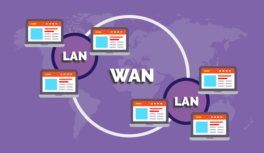
Wide area networks, or shortly known as WANs, would be providing network communication services in the workplace, connecting locations that could be spread out anywhere in the world. A topology is considered to be a description of a layout or arrangement. Applying the concept of topologies to WANs would be involving two different but interrelated perspectives. One perspective to consider is the physical topology, which would be describing the physical arrangement of network devices that would be allowing the data to move from a source to a destination network. Another perspective is the logical topology, which would be describing how data moves over the WAN. Before we move on to the types of WAN Topologies, if you are looking forward to make your career in the IT Sector, you should check out the IT Certification courses offered at the SPOTO Club.
Types of WAN Topologies:
Flat
A small company which would be having few locations might implement a flat topology. This design utilizes point-to-point circuits between the physical locations, forming a loop. For a company which has four locations, each site might be connected on the WAN to two other sites which would be located in different states or countries. The physical transport utilized for a flat WAN could involve leased lines, microwave as well as fiber optic service.
Star
A star topology would be linking a central location serving as the hub in the design, with sites branching off the hub such as spokes on a wagon wheel. In a star topology, a failure to one hub location won’t affect the other sites on the WAN. Due to the importance placed on the central location would be serving as the hub, this site would be benefitting from redundant routers. A hub site would be designed with a single WAN router introduces a single point of failure that would take down the entire WAN. For providing for survivability if a hardware failure is going to occur at the hub site, introduce a dual router design.
Full Mesh
A full mesh topology would be relying on every site’s WAN router having a connection to every other site on the WAN. Full mesh topologies would be able to provide a high degree of dependability as well as fault tolerance, which could come at quite a high price tag. As a company would be growing in size, a full mesh topology would be becoming expensive due to the quantity of physical WAN circuits required as well as the router specifications for supporting the design. An additional complexity could be found in trouble-shooting the design if a problem occurs.
Partial Mesh
A deviation to a full mesh involves a partial mesh topology. This design is going to introduce a hierarchical approach to the topology that could be applied when designing international networks, offering flexibility to establish variations in the topology for meeting geographic needs. WAN access sites would be connected to regional points of concentration, which then would be connected to a headquarters site with a central data center. A partial mesh is considered to be more cost effective than a full mesh. Companies could design a partial mesh topology that would be meeting the needs of their environment while factoring fault tolerance, scalability as well as budget planning.
Now, that you have acquired the knowledge regarding the WAN Topologies and its Types, you should also check out the IT Exam Dumps offered by the SPOTO Club. SPOTO Club would be offering their candidates 100% real and valid exam dumps, which would be able to help you out in clearing any of your IT Certification exam in the very first attempt.
-
- Cisco
- 700
- 2024-01-17
NTP (Network Time Protocol) is considered to be a protocol, which would be utilized for synchronizing computer clock times in a network. It would be belonging to and is considered to be one of the oldest parts of the TCP/IP protocol suite. The term NTP would be applying to both the protocol as well as the client-server programs that would be running on computers. NTP was developed by David Mills at the University of Delaware in 1981 and is designed to be highly scalable and fault-tolerant.
How does NTP work?
The NTP client would be initiating a time-request exchange with the NTP server. As a result of this exchange, the client would be able to calculate the link delay as well as its local offset and adjust its local clock for matching the clock at the server's computer. As a rule, six exchanges over a period of about 5 to 10 minutes would be required for initially setting the clock.
Once synchronized, the client would be updating the clock about once every 10 minutes, basically would be requiring only a single message exchange additionally to client-server synchronization. This transaction would be occurring via the User Datagram Protocol on port 123. NTP would be also supporting broadcast synchronization of peer computer clocks. So, before we get to the features of NTP, if you are looking forward to appearing in the IT Certification Exam, you should opt for the training courses which are offered at the SPOTO Club.
Features of NTP
NTP servers, of which there would be thousands around the world, having access to highly precise atomic clocks as well as GPS clocks. Specialized receivers would be required to directly communicate with the NTP servers for these services. It isn’t practical or cost-effective for equipping every computer with one of these receivers. Instead, computers would be designated as primary time servers would be outfitted with the receivers, as well as they would be utilizing protocols like NTP to orchestrate the clock times of networked computers.
NTP would be utilizing UTC (Universal Coordinated Time) for synchronizing computer clock times with extreme precision, offering greater accuracy on smaller networks down to a single millisecond in a local area network as well as within tens of milliseconds over the internet. NTP doesn’t account for time zones, instead of relying on the host for performing such computations.
Hierarchy of time servers
Stratum levels
Degrees of separation from the UTC source would be defined as strata. A reference clock that would be receiving true time from a dedicated transmitter or satellite navigation system is categorized as stratum-0; a computer that would be directly linked to the reference clock is stratum-1; a computer that would be receiving its time from a stratum-1 computer is stratum-2, and so on. Accuracy would be reduced with each additional degree of separation.
In terms of security, NTP would be known to the vulnerabilities. The protocol could be exploited as well as utilized in denial-of-service attacks for two reasons:
First, it would be replying to a packet with a spoofed source IP address;
Second, at least one of its built-in commands would be sending a long reply to a short request.
Why is NTP important?
Accurate time across a network is considered to be quite important for many reasons; discrepancies of even fractions of a second could cause problems. For example, distributed procedures could be dependent on coordinated times for ensuring proper sequences are followed. Security mechanisms would be depending on consistent timekeeping across the network. File-system updates would be carried out by several computers also depending on synchronized clock times.
If you wish to acquire more knowledge regarding the NTP, SPOTO Club is the best training provider for you.
-
- Cisco
- 824
- 2024-01-18
Foreword
BGP ring defense is implemented through AS_PATH, and AS_PATH is only changed when the route leaves the AS. Therefore, within the AS, IBGP does not have EBGP ring defense capabilities. In order to prevent the occurrence of loops, BGP routers will not be from IBGP neighbor The learned routes are advertised to other IBGP neighbors.
BGP stipulates that the routes learned through one IBGP will not be propagated to all other IBGP neighbors. This is the BGP split horizon rule.
Due to the principle of split horizon, BGP requires that within the AS, IBGP must be fully interconnected (here it is specified by the neighbor command). (The root cause is that within the AS, the AS-PATH will not change and the AS_PATH anti-ring cannot be used, so loops are prone to occur)
Split horizon: R3 does not send to other IBGP neighbor R2 after receiving the update from IBGP neighbor R4. As a result, R2 and R1 cannot get the route of R4
It is also split horizontally, both in BGP and IGP; then:
IGP split horizon: The routing information learned from an interface will no longer be advertised from that interface. It is from that mouth that no longer comes out from this mouth.
Horizontal split of BGP: The routing information learned from any IBGP neighbors is no longer forwarded to any IBGP router. To put it bluntly is a dead end, no longer in control.
So, someone asked, since the same is horizontal split, why are the standards different?
IGP can also send updates to other routers, is BGP too worried? If BGP is right, does IGP cause a loop?
Answer:
Yes! IGP still has a loop to do so! However, this loop is a loop of a large network, so IGP uses other methods to solve this problem, such as the 16-hop RIP (otherwise, if a horizontal split is all done, RIP does not need the 16-hop setting); the reason is The horizontal split of IGP is just to prevent problems in a small area such as regional networks (such as adjacent routers). If the network is large and the interconnection is complicated, loops may still occur.
This situation is intolerable for BGP, a protocol that carries such core and large-scale routing. There is no need to explain this point. Therefore, BGP adopts such a brutal version of horizontal splitting.
How to solve the problem that split horizon causes R4 and R2 to fail to get the route. So how to solve this kind of problem?
Option One
Let the routers in the AS domain be physically fully connected, add a physical link between RTB and RTC, and establish an IBGP neighbor relationship between RTC and RTB, so that RTC can directly pass its own route to the RTB router. The RTB router directly passes the route to RTA through the EBGP neighbor relationship. This fully connected network deployment solution, on the one hand, has a high networking cost, and on the other hand, the increase in the number of BGP connections correspondingly increases the resource consumption of the system, and the fully connected network deployment has poor scalability.
Is there a simpler way?
Option II
Make the routers in the AS domain fully logically connected, make the IGP routes of RTB and RTC reachable to each other, establish an IBGP neighbor relationship between RTB and RTC, so that RTC can directly pass its own route to RTB router, which is directly Routes to RTA through EBGP neighbor relationship.
The ultimate solution-RR
No need to add physical link or new IBGP neighbor relationship-configure BGP route reflector. The RTD is configured with a route reflector, and both RTB and RTC configure a reflector RTD client. In this way, according to the reflector's route reflection principle, RTC can easily reflect its own route to RTB, and RTB passes the EBGP neighbor relationship. Modified application network diagram:
Route Reflector (RR): Allows the routes learned from IBGP peers to be reflected to BGP devices of other IBGP peers.
Client: IBGP device that forms a reflection neighbor relationship with RR. Within the AS, the client only needs to be directly connected to the RR.
Non-Client: IBGP device that is neither an RR nor a client. Between the non-client and RR within the AS,
The purpose of the route reflector (RR) is to simplify the configuration of IBGP neighbors. After using the reflector, it allows the reflector to send routing information from the IBGP neighbor to another IBGP neighbor or a group of neighbors. The router allows the router configured as a route reflector to transmit the routes learned by IBGP to other IBGP peers to modify the horizontal isolation rules of BGP, so that fully interconnected IBGP peers are no longer needed.
Reflection function
The route reflector will reflect the information between the clients in turn. The route reflector and all its clients form a group. Multiple route reflectors are allowed in a group. A route reflector can configure other route reflectors as its clients or non-clients; a route reflector transmits route updates between its clients and non-clients Rules: If the route update is received from a non-client, it is only reflected to the client; if the route update is received from a client, it is reflected to all non-clients and clients, except for the originator of this route update ; If the routing update is received from the EBGP neighbor, it will be reflected to all clients and non-clients.
Reflection process
Public network route BGP route delivery process
Pass a route from RTC to the RTA router through the route reflector, RTA Router ID is 1.1.1.1, RTB Router ID is 2.2.2.2, RTD Router ID is 3.3.3.3, RTC Router ID is 4.4.4.4. RTC publishes a route 4.4.4.4/32 to the IBGP reflector. The reflector RTD learns the route and reflects the route 4.4.4.4/32 to the client RTB.
RTD:
Sh ip bgp route 4.4.4.4
BGP local router ID:3.3.3.3
Local AS number:
Path:1 available,1 best
BGP routing table entry information of 4.4.4.4/32
RR-client route
From:30.0.0.2 (4.4.4.4)
Relay Nexthop:0.0.0.0
Original nexthop:30.0.0.2
AS-path:(null)
Origin:incomplete
Attribute value:MED 0, localpref 100,pref-val 0,pre 255
State:valid,internal,best,
Advertised to such 1 peers:20.0.0.1
The client RTB learns the 4.4.4.4/32 route reflected by the reflector. The Originator of the route is 4.4.4.4 (that is, RTC router), and the Cluster list is 3.3.3.3 (that is, the route is reflected by the reflector RTD router) , Original nexthop is 30.0.0.2 (the route initiates the next hop), Relay Nexthop is 20.0.0.2 (the route relays the next hop).
RTB:
Sh ip bgp route 4.4.4.4
BGP local router ID:2.2.2.2
Local AS number:100
Path:1 available,1 best
BGP routing table entry information of 4.4.4.4/32
RR-client route
From:20.0.0.2(3.3.3.3)
Relay Nexthop:20.0.0.2
Original nexthop:30.0.0.2
AS-path:(null)
Origin:incomplete
Attribute value:MED 0,localpref 100,pref-val 0,pre 255
State:valid,internal,best,
Originator:4.4.4.4
Cluster list:3.3.3.3
Advertised to such 1 peers:10.0.0.1
The RTA router learned the route 4.4.4.4/32 through the EBGP neighbor relationship.
RTA:
Sh ip bgp route 4.4.4.4
BGP local router ID:1.1.1.1
Local AS number :200
Path:1 available,1 best
BGP routing table entry information of 4.4.4.4/32
From:10.0.0.2 (2.2.2.2)
Original nexthop:10.0.0.2
AS-path:100
Origin:incomplete
Attribute value:pref-val 0,pre 255
State:valid,external,best,
Not advertised to any peers yet
In this way, the route reflector successfully shields the BGP horizontal isolation rules and passes the route to the RTA router.
Route reflector (RR) configuration:
①: Enable BGP
②: Establish neighbors under the same BGP-AS.
③: Specify the router and the AS where it is located.
④: Specify the source.
⑤: (neighbor) RR client-configure the client.
⑥:neighbor router-id route-reflector-client
RTD:
Router bgp 100
bgp router-id 3.3.3.3
neighbor 2.2.2.2 remote-as 100
neighbor 4.4.4.4 remote-as 100
neighbor 2.2.2.2 route-reflector-client
neighbor 4.4.4.4 route-reflector-client
Note: if you are interested in the article, and you can follow SPOTO. And, you want to take any certifed exam, and you can contact us now!
-
- Cisco
- 879
- 2024-01-18
Why do you need port security?
IP address spoofing:
Refers to the IP packet generated by the operation as a forged source IP address in order to impersonate the identity of other systems or senders. This is a form of hacker attack. The hacker uses a computer to surf the Internet and borrows the IP address of another machine, thereby posing as another machine to deal with the server. The firewall can recognize this ip spoofing.
According to the Internet Protocol (IP), the packet header contains source and destination information. IP address spoofing is to forge the header of the data packet so that the displayed information source is not the actual source, just as this data packet was sent from another computer.
IP attack steps:
(1) First, temporarily paralyze the network of the trusted host to avoid causing harassment to the attack;
(2) Then connect to a port of the target machine to guess the ISN base value and increase law;
(3) Next disguise the source address as a trusted host and send a data segment with the SYN logo to request connection;
(4) Then wait for the target machine to send the SYN + ACK packet to the host that has been paralyzed;
(5) Finally, pretend to be the ACK sent by the trusted host to the target again, and the data segment sent at this time carries the predicted ISN + 1 of the target;
(6) The connection is established and a command request is sent. (The connection is established, but only commands can be sent, and no echo is received, because the server echoes to the truly trusted host according to the IP)
What is Port-security
concept:
The switch learns the source MAC address, and maps the source MAC address to the interface learned to the address in a table. This table is called the MAC address table and forwards Ethernet frames based on the target MAC address. Under normal circumstances, an interface can correspond to multiple MAC addresses, in order to better control the number of MAC addresses on the switch interface and the specific MAC address, you can use port security to control.
Port Security can control the correspondence between a specific interface on a switch and a specific MAC address, and can also limit the maximum number of MAC addresses on an interface. The interface with the port security function is called a secure port. Only the traffic with a pre-defined MAC address, that is, legitimate traffic, is forwarded on the secure port. Traffic with other MAC addresses (violating traffic) is rejected.
Policy violation
When the MAC address on the interface reaches the maximum allowed MAC address limit, if there are other MAC addresses to be accessed, it is considered a violation.
The MAC address defined on a secure port is also illegal when accessed on another secure port, that is, the specified MAC address can only appear on the specified port, and it appears to be illegal on other ports.
The secure port will only allow packets whose source MAC address is a secure MAC address, and other MAC addresses that violate the rules will be rejected.
Set penalties after violation
shutdown // The port becomes err-disable, which is equivalent to shutting down the port, which is the default processing method
protect // Discard the packets with illegal MAC addresses, but the port is in UP state. The switch does not record violation packets
Restrict // Discard the packets with illegal MAC addresses, but the port is in UP state. The exchange records the violation group (equivalent to credit credit)
Basic configuration
Requirements: R2 \ R3 \ R4 are directly connected network segments, which can be set arbitrarily, and configure port security on e0 / 0 of the switch
Test before configuration:
Test 1: R1 \ R2 \ R4 should be able to ping each other
Test 2: The attacker connects to any other interface of the hub to imitate the address of R1 and ping R2 to be able to ping, and then delete or close the interface connecting the hacker to the HUB.
Configuration
Activate Port-Security (on the access \ trunk interface)
interface Ethernet0/0
switchport mode access
switchport port-security
// The interface that enables port security cannot be in dynamic negotiation (dynamic) mode, and must have mode trunk or mode access. Once the Port-Security feature of the interface is activated, the default maximum number of security addresses is 1, which means that In the case of manually configuring a secure address, this interface will use the dynamically learned MAC as the secure address, and this interface is equivalent to being exclusively occupied by the MAC (the device it belongs to). And the default violation is shutdown
SW1#show port-security interface f0/1
Port Security : Enabled
Port Status : Secure-up //The current state of the interface is up
Violation Mode : Shutdown // Penalties after violation, default is shutdown
Aging Time : 0 mins
Aging Type : Absolute
SecureStatic Address Aging : Disabled
Maximum MAC Addresses : 1 //Maximum Security number address, the default is 1
Total MAC Addresses : 0
Configured MAC Addresses : 0 //Manually statically configured secure MAC address
Sticky MAC Addresses : 0 !! sticky's secure address
Last Source Address:Vlan : 00b0.1111.2222:10 //The nearest safe address + vlan
Security Violation Count : 0 !! Number of violations that have occurred in the history of this interface
At this time, if another PC is connected to this port, the port-security interface will receive a new, non-secure address entry MAC address data frame, so the triggered illegal action is given to the interface Will be err-disable. At the same time, a snmp trap message is generated. In addition, under the interface, Security Violation Count will increase by 1.
Configure the maximum number of allowed security addresses for Port-Security
switchport port-security maximum 4
// Configure the maximum number of active addresses allowed by the interface and the maximum number of safe addresses. The upper limit allowed by different software platforms is different, but the default is 1.
On the trunk port, port-security can be activated, and the maximum number of security addresses configured on the trunk port can be based on the interface configuration (effective for all VLANs)
Use sticky MAC address on the port-security interface
switchport port-security mac-address sticky
//We know that there are several ways to form a secure address table entry, one of which is manual configuration using switchport port-security mac, but this method is time-consuming and labor-intensive, and requires a MAC to be copied from the PC, and the work cost is relatively high . Another way to form a secure address is to let the switch use the dynamically learned MAC, but these secure addresses will be lost once the interface is up / down, let alone restart the device. Therefore, you can use the sticky mac method. After this method is activated, the switch “sticks” the dynamically learned MAC. The specific action is very simple. After dynamically learning the MAC, if I activate the sticiky MAC address, then A command is automatically generated under the interface:
switchport port-security mac-address sticky aabb.cc00.3400
switchport port-security mac-address sticky aabb.cc00.7400
switchport port-security mac-address sticky aabb.cc00.b400
The secure address table entry (which is SecureSticky) formed in this way will not be lost even if the interface is flipped. If the wr saves the configuration and the command is written to config.text, the safe address will not be lost even if the device restarts.
Test
At this time, the hacker will access the HUB and imitate the address of R1 to test the ping R2,Because the switch has been bound to the mac address, the hacker cannot ping.
-
- Cisco
- 679
- 2024-01-16
Introduction
EIGRP is a Cisco proprietary protocol. It is a protocol composed of two routing protocols: distance vector and link state. That is, like the distance vector protocol, EIGRP gets update information from its neighboring routers; like the link state protocol, it saves a topology table, and then selects an optimal acyclic path through its own DUAL algorithm. EIGRP is not like the traditional distance vector protocol, EIGRP has a fast convergence time, and does not need to send periodic routing updates; unlike the link state protocol, EIGRP does not know what the entire network is like, it can only rely on neighbors to announce Information. EIGRP uses the same routing algorithm DUAL (Diffusion Update Algorithm) as IGRP. The DUAL mechanism is the core of EIGRP, through which loop-free paths are realized. The internal EIGRP management distance is 90 and the external EIGRP management distance is 170, which supports equal and non-equivalent load balancing. In IP packets, the EIGRP protocol field is 88.
Glossary:
Metrics: EIGRP use bandwidth (bandwidth), delay (delay), reliability (reliability), loading (loading), maximum transmission unit
(MTU) These five values are used to calculate the metric. By default, only bandwidth and delay are in effect. The calculation formula is-EIGRP metric = [(10 ^ 7 / path
Lower bandwidth on +) + (sum of all delays)] × 256; EIGRP metric = IGRP metric × 256.
Feasible Distance: The smallest metric to reach a destination.
Advertisement Distance (Advertise Distance): The minimum metric value advertised by the neighboring router to reach a certain destination.
Feasible Condition: The condition that the advertised distance (AD) is less than the feasible distance is AD <FD, which means that the neighboring router reaches the destination
The metric of the ground must be smaller than the metric of the local router to reach the destination. This condition can ensure that a path is loop-free.
EIGRP Successor: A directly connected neighbor router that satisfies the FC and passes the path with the smallest metric value to its destination
By device. The successor router is used as the next hop to forward the message to the destination.
Feasible Successor: A neighbor router that meets the FC and has the second lowest metric to the destination router. Be the master
When route S is unavailable, FS is used to replace the main route, so it is saved in the topology table and used as a backup route.
Active state / active routing (active state): It is a state of searching for FS. When the router loses S and no FS is available, the
The route entered an active state and is an unavailable route. When a route is active, the router sends a query to all neighbors to find
Find another route to this destination.
Passive state / passive routing (passive state): It is a state where the correct route currently reaches the destination. When the router loses S, there is a
When an FS is found, or when another S is found, the route enters a passive state and is an available route.
Neighbor relationship: EIGRP establishes a neighbor relationship through hello packets. The transmission interval of hello packets is 60 seconds on low-speed links and 5 seconds on high-speed links.
If the hello packet is not received within a period of time, the neighbor relationship is reset. This time is the hold time, and the default hold time
It is three times the hello time. Both times can be modified manually. When establishing a neighbor relationship, the K value and the self-made system number must be the same. can
Check the neighbor relationship through show ip eigrp neighbor.
Experimental topology
IP address planning
1. The IP address segment in the topology is adopted: 172.8.AB.X / 24
2. Where AB is the combination of two router numbers, for example: AB between R3-R6 is 36, X is the router number, for example: R3 X = 3
3. The network segment between R1 / R2 / R5 is: 172.8.123.X / 24, where X is the router number.
4. The network segment between R4 / R5 / R6 is: 172.8.100.X / 24, where X is the router number.
5. All routers have a loopback 0 interface, the address format is: X.X.X.X / 32, where X is the router number.
Testing Requirement
R4 / R5 / R6 are connected through a Layer 2 switch. According to the experimental topology diagram, declare the router interface to the corresponding EIGRP process. If there is no specific description, you can declare it arbitrarily. It is required to turn off automatic aggregation.
2.R2 --- E3RP authentication is enabled on R3 (MD5 is used for authentication), the password is: SPOTO
There is a Loopback 1 interface on R1. The IP is: 199.172.1.254/24, 199.172.2.254/24, 199.172.3.254/24 (using the secondary method to configure IP), and announce them to EIGRP 100. To summarize the addresses of R1's Loopback1 interface on R1 and observe the routing table on R2.
The router in EIGRP AS 8 is required to receive the summary route of R1.
This summary route from R6 to R1 is required to achieve unequal cost load balancing.
Configure R2 and R5 so that they will not receive any EIGRP query information under the EGRIP 100 process, and will not send any routing information about them to their EIGRP 100 neighbors.
It is required to use up to 2 static routing entries to achieve inter-network communication.
Case configuration ideas and test results
R4 / R5 / R6 are connected through a Layer 2 switch. According to the experimental topology diagram, declare the router interface to the corresponding EIGRP process. If there is no specific description, you can declare it arbitrarily. It is required to turn off automatic aggregation.
There is a Loopback 1 interface on R1. The IP is: 199.172.1.254/24, 199.172.2.254/24, 199.172.3.254/24 (using the secondary method to configure IP), and announce them to EIGRP 100, using manual summary To summarize the addresses of R1's Loopback1 interface on R1 and observe the routing table on R2.
The router in EIGRP AS 8 is required to receive the summary route of R1.
The summary route from R6 to R1 is required to achieve unequal cost load balancing.
Configure R2 and R5 so that they will not receive any EIGRP query information under the EGRIP 100 process, and will not send any routing information about them to their EIGRP 100 neighbors.
It is required to use up to 2 static route entries to achieve inter-network communication.